Project AVOID Part 3; Inclines
With the development and testing of the AVOID (Attenuating Vehicular Obstacle Interference Design) rock avoidance sensor complete, we moved onto the next sensor; one that could detect inclines. The specifications of these inclines are described in the challenge guidelines as:
Slopes greater than 30 degrees (either up or down hill)
herox.com
Research into tilt sensor designs revealed that the most widely used form was that of a small spherical weight placed inside a tube. When the tube was tilted the weight would roll into the bottom of the tube, touch a pair of wires located there and trigger the sensor. While this design does work, it is not suitable as a solution for the challenge as it relies on the use of electricity to transmit the sensor activation signal, an activation method that is not compatible with the challenge’s pin based mechanical system.
Fortunately, a potential solution quickly presented itself. The use of a pole that when pushed by the weight would be ejected from the sensor and then alert the rover by pushing the activation pin that the sensor would be directly attached too. This idea was quickly proved to be flawed after the 3D printing and subsequent testing of a prototype of the sensor. Testing of this prototype revealed that while it did function as intended, the movement of the weight in the sensor did not produce anywhere near enough force to move the rover’s pin.
This discovery meant that we had to come up with a different method to move the pin with the needed force, while still using a tilt sensor that only produced the minuscule force of a rolling ball. With further examination of the challenges guidelines we found another possible method for moving the pin that would be sufficient. In the challenge, a small selection of outputs are available from the rover to support the operation of the sensor. One of these outputs is a rotating pole that’s speed and toque can be customized to fit the sensors needs. This pole provided the opportunity to increase the force applied by the tilt sensor while still using the semi-viable rolling ball varient previously tested.
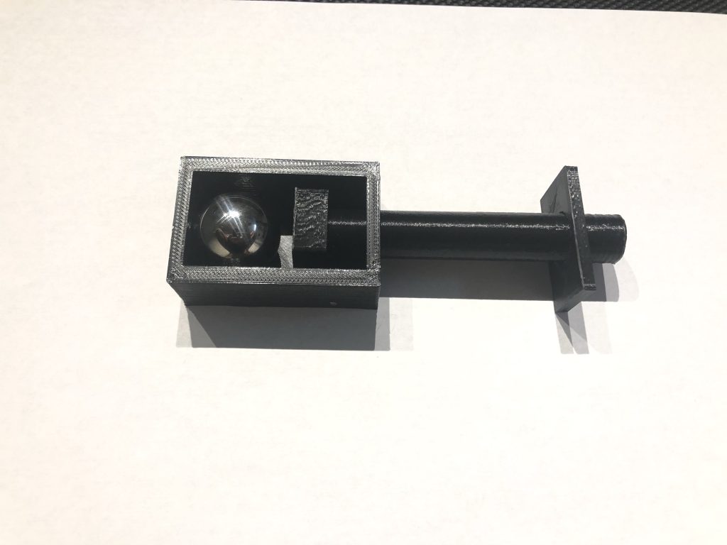
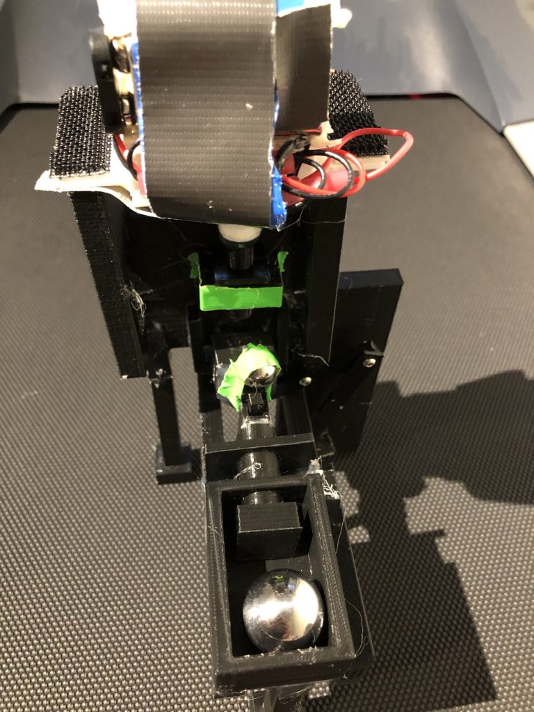
To generate this extra force, the purpose of the ball’s force would change from that of a trigger to the operation of a component similar in function to a gear shifter in a manual car. This new sensor would use the force of the pole to constantly spin a mechanism, that would have more than enough force to trigger the pin, yet be intentionally designed to be unable to reach the pin to avoid consistently triggering the pin. Then, when the rover tilts to a sufficient level to necessitate triggering the sensor, the ball will roll inside the sensor, and push a small block into the mechanism, temporarily increasing it’s reach enough to trigger the pin.
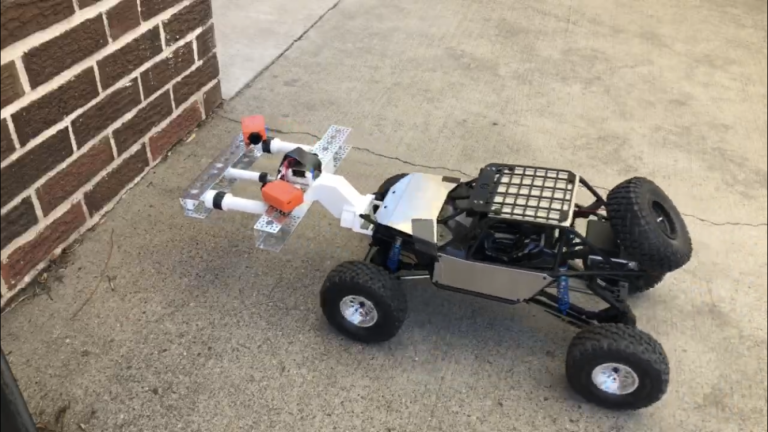
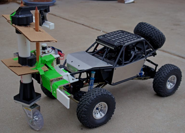
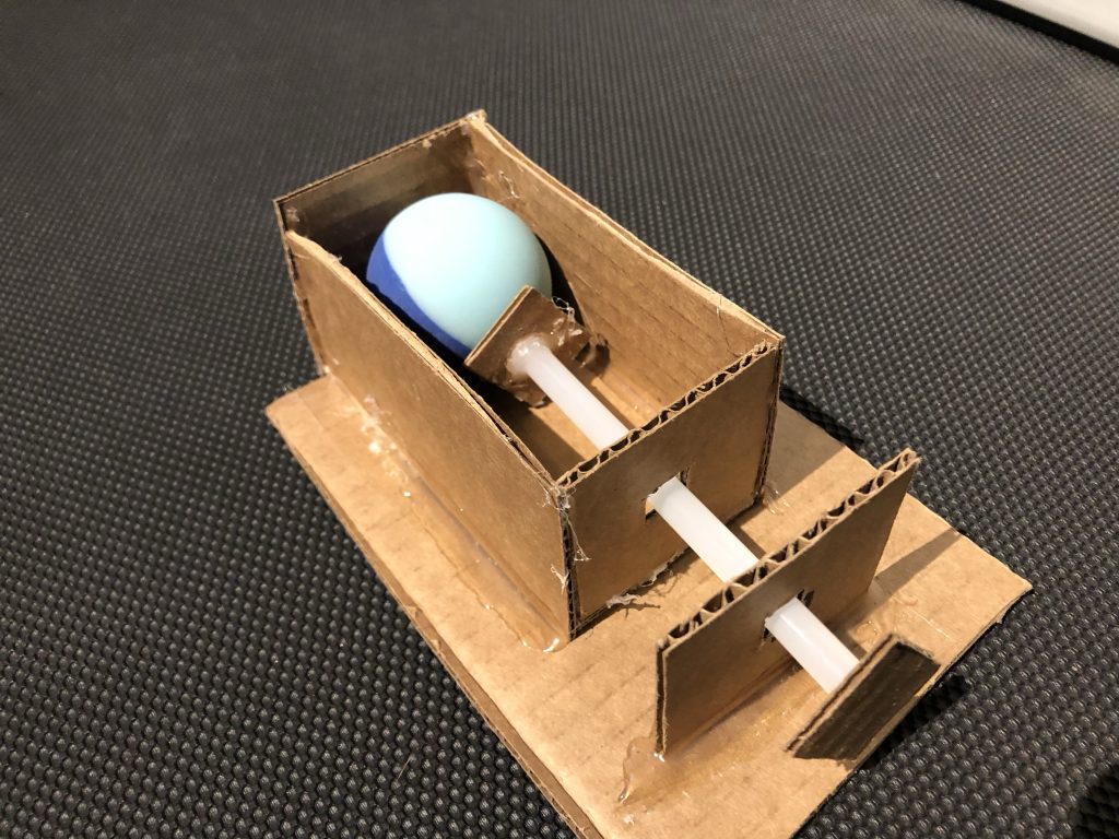
At this point, we had a plausible concept for how this sensor could function, but once again needed to test it to confirm it would operate as expected under real world conditions. Utilizing a mix of 3D printed parts and reclaimed cardboard we built a model of the sensor and performed several tests of it.
These preliminary tests proved mostly successful, although the flexibility of the cardboard prevented us from reaching a conclusive result. Regardless of these shortcomings, the tests proved enough evidence that this sensor design could be viable and we felt confident that we could safely move on to the creation of a fully 3D printed version to for further testing.
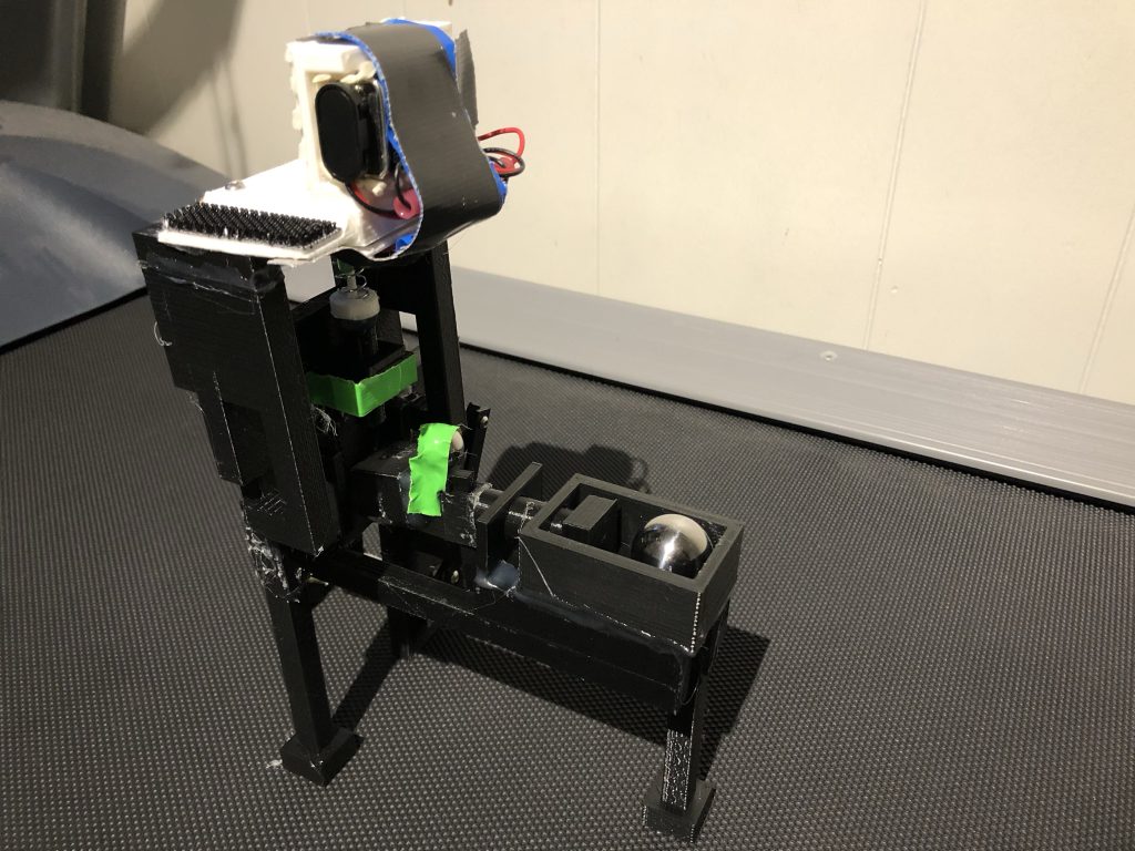
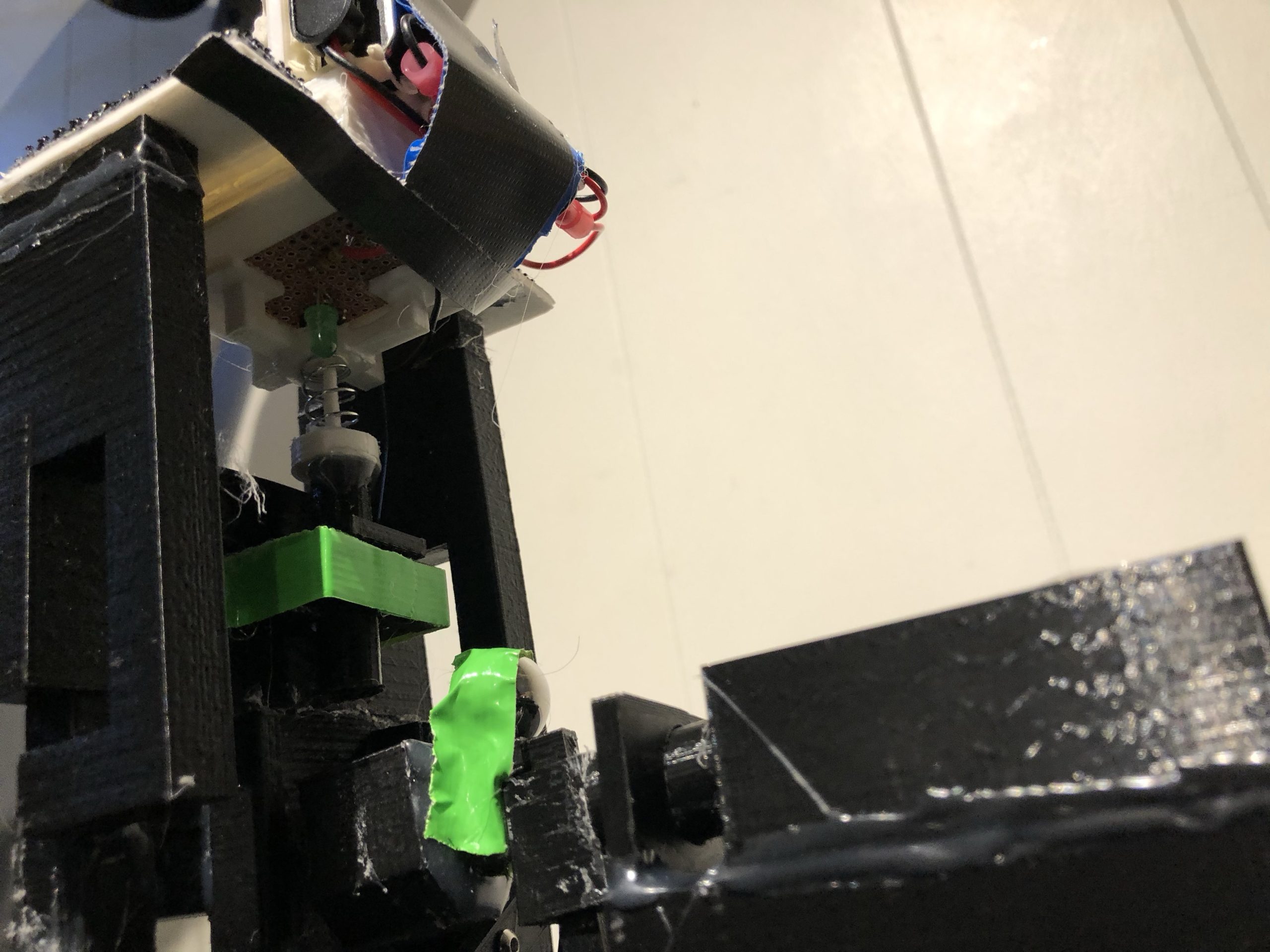
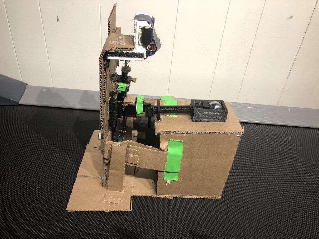
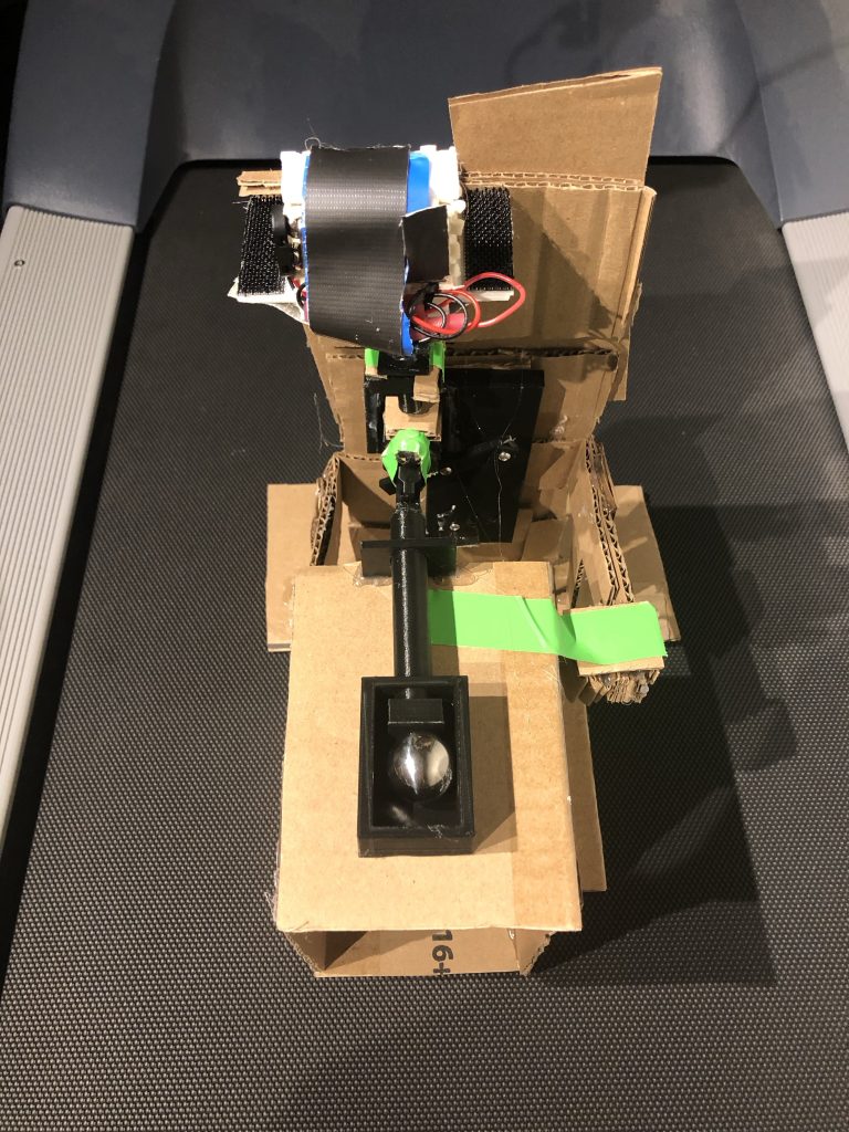
After a few days of work we had the new 3D printed prototype of the tilt sensor almost complete and ready for testing. All that remained was the installation of a motor that would be used to replicate the movement of the pole that would occur during rover operation. A suitable motor was quickly found, purchased, added to the tilt sensor and mounted to the GTS (Ground Test System) for testing.
This test proved that the tilt sensor functioned as expected. Now with this sensor conplete we had only one more to do.