Electronics
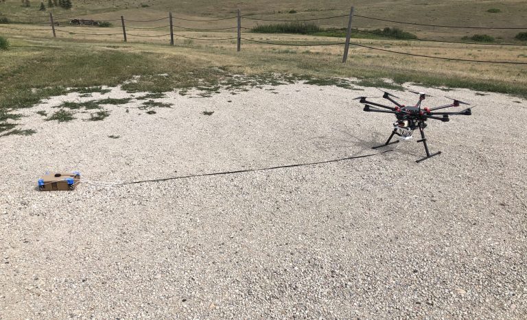
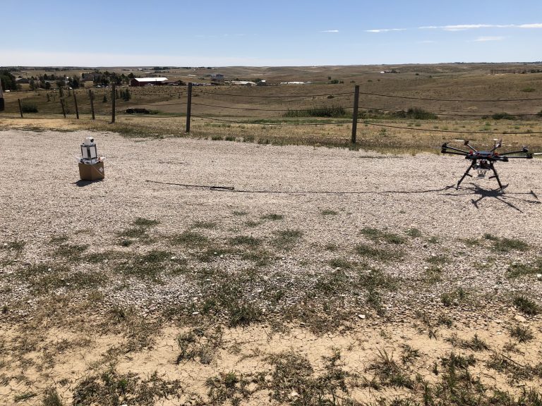
We have been continuing our preparations for the first test flight of the GTP (Guidance Test Payload) that will signal the start of the development of the guidance system. Our efforts in the past weeks have been focused in three different areas.
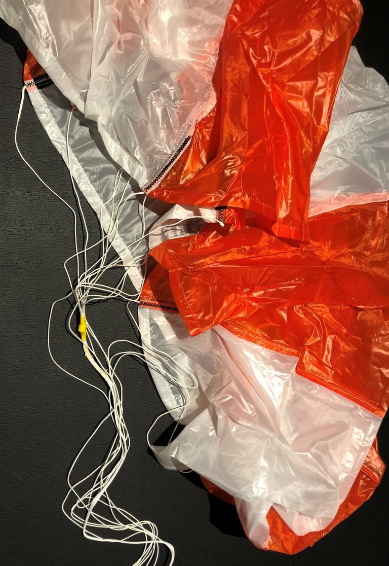
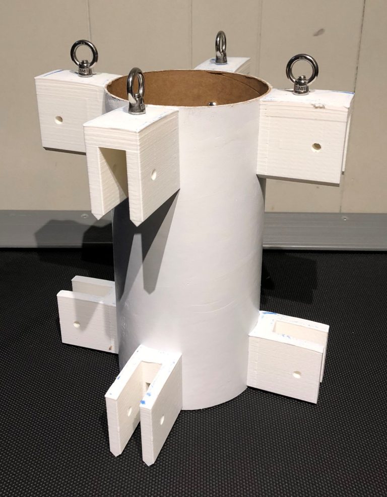
First, with the completion of the internal parachute module and the painting of the outer shell last month, we are now ready to start working on the components that will be attached to the exterior of the shell. During the first few tests of the GTP, we will be dropping it with a wide variety of fin designs to determine the most optimal configuration. Due to this, we need a system to attach the fins that allows us to quickly and easily switch fins. The fin attachment points we designed will consist of 8 fin holders that will be mounted to the top and bottom of the parachute module’s shell. The top fin attachment points will also have brackets that will provide a secure connections for the parachute lines. We were able to print all 4 top fin attachment points before we ran out of printing material and were forced to wait for more to arrive.
The second area of development was focused around the electronics module. This involved prepping the shell in much the same way as the parachute segments and the designing of a part we call the cone coupler. This part sits between the internal electronic module and the nose cone of the GTP and keeps these parts together during flight and landing. While at first glance the cone coupler may seem to a simple part, it proved to be anything but. Due to the size of it and the limited capability of our 3D printer we were forced to print it in two parts and attach them after they were printed. It also took several tries to get the angle of the cone coupler to match the angle of the nose cone. Even after all this was done and the parts were printed, we still had trouble with the alignment of the holes in the cone coupler and the internal electronic module. A few modifications with a drill quickly solved this problem. With all these parts assembled the internal electronic module was now complete (a picture of this can be seen at the top of this post.).
Our third and final area of focus has been the research into, and the acquisition of parts for, the PSCC (Parachute System Control Computer). This is one of the many computers we need to develop and as the name suggests, its function is to automatically deploy the parachute at a preset altitude. The most obvious use for this computer is on the final HAB (High Altitude Balloon) payload, but it will also be very useful during the test flights of the GTP as it can take some of the load off the operator of it by removing the need for them to decide when to deploy the chute. Unlike the cameras we experimented with previously, we plan to use an arduino as a base for the PSCC. As for sensors, a mix of GPS, air pressure and temperature sensing capabilities are planed. We hope that by using a wide variety of methods to determine the altitude of the PSCC, the accuracy and reliability of the system will be increased.
In the coming weeks, we plan to attach the fins to the GTP, paint the electronic modules shell and begin assembly of the PSCC.